Doubling Effect
When transformers are energised (or when a transformer primary is switched on to the supply source), a transient inrush current up to 10-50 times the rated transformer current can flow and may last for several cycles. The worst condition exists when the transformer is switched on at or around the zero crossing of the voltage wave form. This inrush current can cause malfunctioning or unwanted tripping of the primary protective devices. The magnitude and duration of the inrush current depends on the following factors :
1) Size of the transformer bank
2) Size of the power system as well as the magnitude, and ratio of inductance to resistance of the system from source to the transformer bank
3) Type of iron used for the core
4) Previous history of the core (residual flux), initial recovery of the sympathetic flux wave,etc.
Hence it is very essential that a careful analysis of the characteristic is made in selective the primary protective device for transformer. The relationship between the capacity of the transformers with the time constant of the inrush current and the ratio of inrush current to be the normal current for oil filled and cast resin type transformers respectively.
The relation between the primary current threshold setting and the time delay setting of the protective device is shown in the Fig. 1, where the y-axis represents the ratio of time delay setting to the inrush time constant and the x-axis represents the ratio of setting threshold of primary current to the inrush current.
Consider for example a 500 KVA oil filled transformer with a voltage ratio of 11 KV/433 V ans suitable for 50 Hz three phase operation.
The ratio of inrush to rated primary current Ki = 12
Time constant of the inrush current = 0.25 sec
Full load rated current on the primary = 26.2 A
The inrush current = 12 x 26.2
= 314.4 A
Assuming a setting threshold for primary current I't of 35 A
I't/IPinrush = 35/314.4 = 0.111
From Fig 1, corresponding to I't/IPinrush = 0.111, the ratio tr /τinrush =1.8
Therefor,time delay setting = 1.8 x 0.25 = 0.45 seconds.
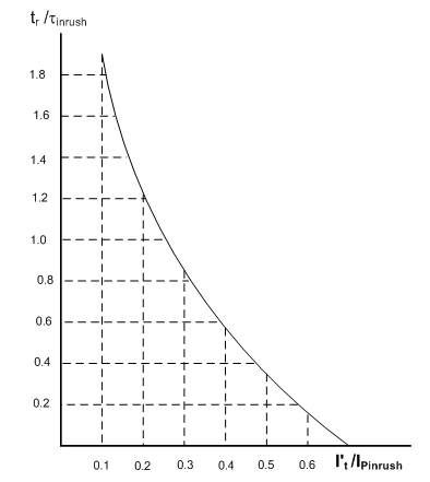
Fig. 1 Relation between threshold setting and time delay setting
Table 3 Fuse rating in the primary side of transformers (11 KV/433 V)

This is the minimum time delay required by the primary protective device to avoid unwanted tripping or malfunctioning of the protective device on the primary side, the fuse manufacturers provide information regarding the minimum and maximum size of the high voltage fuse ratings. Table 3 provides a typical data of the fuse ratings on the primary side of transformers.
Current inrush phenomenon ( Switching transient )
In the steady state operation, both V1 and Φ are sinusoidal and Φ lags V1 by 90°as shown in the Fig.2.

Fig. 2
When the primary voltage V1 is switched on to the transformer, the core flux and the exciting current undergo a transient before achieving the steady state. They pass through a transient period. The effect of transient is severe when voltage wave pass through origin.
In the inductive circuit flux can start with zero value. But the steady state value of flux at start is -Φm , as shown in the Fig. 2, at t = 0. Thus during transients a transient flux called off-set flux, Φt = Φm originates such that at t = 0, Φt +Φss is zero at the instant of switching. This transient flux Φt then decays according to circuit constants i.e. ratio L/R. This ratio is generally very small for transformers.
Thus during transients, the total flux goes through a maximum value of 2Φm. Such effect is called doubling effect. This is shown in the Fig.3.
Due to the doubling effect, core flux achieves a value of 2Φm due to which transformer draws a large exciting current. This is due to the fact that core goes into deep saturation region of magnetisation. Such a large exiting current can be as large as 100 times the normal exiting current. To withstand electromagnetic forces developed due to large current, the windings of transformer must be strongly braced. This large current drawn during transient is called inrush phenomenon.

Fig. 3 Doubling effect
Practically initial core flux can not be zero due to the residual flux Φ'r present, due to retentively property of core. The transient resultant flux goes through Φr = Φ'r + 2Φm and there is heavy inrush current in practice. The effect of transient is even severe in practice.
Such high transient current gradually decreases and finally acquires a steady state. It can last for several seconds. The transient flux Φt and exciting current both are unidirectional during transients. In steady state, exciting current becomes sinusoidal. The Fig. 4 shows the oscillogram of the inrush current.

Fig. 4 Waveform of inrush current

1) Size of the transformer bank
2) Size of the power system as well as the magnitude, and ratio of inductance to resistance of the system from source to the transformer bank
3) Type of iron used for the core
4) Previous history of the core (residual flux), initial recovery of the sympathetic flux wave,etc.
Hence it is very essential that a careful analysis of the characteristic is made in selective the primary protective device for transformer. The relationship between the capacity of the transformers with the time constant of the inrush current and the ratio of inrush current to be the normal current for oil filled and cast resin type transformers respectively.
The relation between the primary current threshold setting and the time delay setting of the protective device is shown in the Fig. 1, where the y-axis represents the ratio of time delay setting to the inrush time constant and the x-axis represents the ratio of setting threshold of primary current to the inrush current.
Consider for example a 500 KVA oil filled transformer with a voltage ratio of 11 KV/433 V ans suitable for 50 Hz three phase operation.
The ratio of inrush to rated primary current Ki = 12
Time constant of the inrush current = 0.25 sec
Full load rated current on the primary = 26.2 A
The inrush current = 12 x 26.2
= 314.4 A
Assuming a setting threshold for primary current I't of 35 A
I't/IPinrush = 35/314.4 = 0.111
From Fig 1, corresponding to I't/IPinrush = 0.111, the ratio tr /τinrush =1.8
Therefor,time delay setting = 1.8 x 0.25 = 0.45 seconds.
Fig. 1 Relation between threshold setting and time delay setting
Table 3 Fuse rating in the primary side of transformers (11 KV/433 V)
This is the minimum time delay required by the primary protective device to avoid unwanted tripping or malfunctioning of the protective device on the primary side, the fuse manufacturers provide information regarding the minimum and maximum size of the high voltage fuse ratings. Table 3 provides a typical data of the fuse ratings on the primary side of transformers.
Current inrush phenomenon ( Switching transient )
In the steady state operation, both V1 and Φ are sinusoidal and Φ lags V1 by 90°as shown in the Fig.2.
Fig. 2
When the primary voltage V1 is switched on to the transformer, the core flux and the exciting current undergo a transient before achieving the steady state. They pass through a transient period. The effect of transient is severe when voltage wave pass through origin.
In the inductive circuit flux can start with zero value. But the steady state value of flux at start is -Φm , as shown in the Fig. 2, at t = 0. Thus during transients a transient flux called off-set flux, Φt = Φm originates such that at t = 0, Φt +Φss is zero at the instant of switching. This transient flux Φt then decays according to circuit constants i.e. ratio L/R. This ratio is generally very small for transformers.
Thus during transients, the total flux goes through a maximum value of 2Φm. Such effect is called doubling effect. This is shown in the Fig.3.
Due to the doubling effect, core flux achieves a value of 2Φm due to which transformer draws a large exciting current. This is due to the fact that core goes into deep saturation region of magnetisation. Such a large exiting current can be as large as 100 times the normal exiting current. To withstand electromagnetic forces developed due to large current, the windings of transformer must be strongly braced. This large current drawn during transient is called inrush phenomenon.
Fig. 3 Doubling effect
Practically initial core flux can not be zero due to the residual flux Φ'r present, due to retentively property of core. The transient resultant flux goes through Φr = Φ'r + 2Φm and there is heavy inrush current in practice. The effect of transient is even severe in practice.
Such high transient current gradually decreases and finally acquires a steady state. It can last for several seconds. The transient flux Φt and exciting current both are unidirectional during transients. In steady state, exciting current becomes sinusoidal. The Fig. 4 shows the oscillogram of the inrush current.
Fig. 4 Waveform of inrush current

I am happy to find your distinguished way of writing the post. Now you make it easy for me to understand and implement the concept. Thank you for the post.
ReplyDeletesearch
This is doubling effect during transients due to short circuit on transmission lines(say yes or no)
ReplyDeleteThank you! very well explained. It helped me.
ReplyDelete