Starters
Introduction
In industrial applications, almost everything uses a motor, in fact, motors may account for up to 80% of our country’s energy usage. There are generally three different ways to start a motor: full-voltage, reduced voltage, and inverter. A full voltage, across-the-line, or direct on-line (DOL) start uses a contactor, which is a heavier duty three-phase relay. Reduced voltage starting can be accomplished via several different ways: auto-transformer, star-delta, primary resistor/reactor, or with a solid state soft starter. Inverters are generally referred to as drives. This paper focuses on solid state soft starters (referred to as soft starter only from here on): what they are, why they are used, their construction, and applications.
Need for Starters in IM
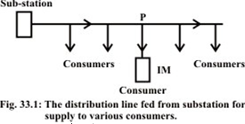
The main problem in starting induction motors having large or medium size lies mainly in the requirement of high starting current, when started direct-on-line (DOL). Assume that the distribution line is starting from a substation (Fig. 33.1), where the supply voltage is constant. The line feeds a no. of consumers, of which one consumer has an induction motor with a DOL starter, drawing a high current from the line, which is higher than the current for which this line is designed. This will cause a drop (dip) in the voltage, all along the line, both for the consumers between the substation and this consumer, and those, who are in the line after this consumer. This drop in the voltage is more than the drop permitted, i.e. higher than the limit as per ISS, because the current drawn is more than the current for which the line is designed. Only for the current lower the current for which the line is designed, the drop in voltage is lower the limit. So, the supply authorities set a limit on the rating or size of IM, which can be started DOL. Any motor exceeding the specified rating, is not permitted to be started DOL, for which a starter is to be used to reduce the current drawn at starting.
Methods of Starting Three Phase Induction Motors
As we know, once a supply is connected to a three phase induction motor a rotating magnetic field will be set up in the stator, this will link and cut the rotor bars which in turn will induce rotor currents and create a rotor field which will interact with the stator field and produce rotation. Of course this means that the three phase induction motor is entirely capable of self starting.
The need for a starter therefore is not, conversely enough, to provide starting but to reduce heavy starting currents and provide overload and no-voltage protection.
There are a number of different types of starter including.
- · The Direct On-line
- · Star-Delta Starter
- · Auto-Transformer
- · Rotor resistance
Direct on line starter

In electrical engineering, a direct on line (DOL) or across the line starter starts electric motors by applying the full line voltage to the motor terminals. This is the simplest type of motor starter. A DOL motor starter also contain protection devices, and in some cases, condition monitoring. Smaller sizes of direct on-line starters are manually operated; larger sizes use an electromechanical contactor (relay) to switch the motor circuit. Solid-state direct on line starters also exist.
A direct on line starter can be used if the high inrush current of the motor does not cause excessive voltage drop in the supply circuit. The maximum size of a motor allowed on a direct on line starter may be limited by the supply utility for this reason. For example, a utility may require rural customers to use reduced-voltage starters for motors larger than 10 kW.
Star-Delta Starter

This is the most common form of starter used for three phase induction motors. It achieves an effective reduction of starting current by initially connecting the stator windings in star configuration which effectively places any two phases in series across the supply. Starting in star not only has the effect of reducing the motor’s start current but also the starting torque. Once up to a particular running speed a double throw switch changes the winding arrangements from star to delta whereupon full running torque is achieved.
Auto-Transformer

A type of reduced voltage starter that uses an autotransformer to allow voltage levels to be reduced to 80, 65, and 50% of full line voltage. Also commonly called a compensator.
This method of starting reduces the start current by reducing the voltage at start up. It can give lower start up currents than star-delta arrangements but with an associated loss of torque.
It is not as commonly utilized as other starting methods but does have the advantage that only three connection conductors are required between starter and motor.
Rotor Resistance Starters for Slip-ring (wound rotor) IM

If it is necessary to start a three phase induction motor on load then a wound rotor machine will normally be selected. Such a machine allows an external resistance to be connected to the rotor of the machine through slip rings and brushes.
At start-up the rotor resistance is set at maximum but is reduced as speed increases until eventually it is reduced to zero and the machine runs as if it is a cage rotor machine.
In a slip-ring (wound rotor) induction motor, resistance can be inserted in the rotor circuit via slip rings, so as to increase the starting torque.
The input (stator) current is proportional to the rotor current as shown earlier. The starting current (input) reduces, as resistance is inserted in the rotor circuit. But the starting torque, [] increases, as the total resistance in the rotor circuit is increased. Though the starting current decreases, the total resistance increases, thus resulting in increase of starting torque as shown in Fig. 32.2b, and also obtained by using the expression given earlier, for increasing values of the resistance in the rotor circuit. If the additional resistance is used only for starting, being rated for intermittent duty, the resistance is to be decreased in steps, as the motor speed increases. Finally, the external resistance is to be completely cut out, i.e. to be made equal to zero (0.0), thus leaving the slip-rings short-circuited. Here, also the additional cost of the external resistance with intermittent rating is to be incurred, which results in decrease of starting current, along with increase of starting torque, both being advantageous. Also it may be noted that the cost of a slip-ring induction is higher than that of IM with cage rotor, having same power rating. So, in both cases, additional cost is to be incurred to obtain the above advantages. This is only used in case higher starting torque is needed to start IM with high load torque. It may be observed from Fig. 32.2b that the starting torque increases till it reaches maximum value.
Energy efficient starter

What is a soft starter?
A soft starter is a solid state motor starter that is used to start or stop a motor by notching the voltage waveform, thereby, reducing the voltage to each phase of a motor and gradually increasing the voltage until the motor gets up to full voltage/speed all at a fixed frequency. The profile of the increase of voltage depends on the application. The voltage is reduced and controlled by 3 pairs of back-to-back silicon-controlled rectifiers (SCRs), which are a type of high speed thyristor. A soft starter takes the place of a contactor and can also take the place of an overload relay in a standard motor starting application.
Why use a soft starter?
In general, there are two reasons to use a soft starter: the power distribution network may not be able to handle the inrush current of the motor and/or the load cannot handle the high starting torque. As a rule of thumb, a motor utilizes around 600-800% of its full load current (FLA) to start. This current is referred to as inrush current or locked-rotor current. If a large motor is on a smaller power distribution network or on a generator system, this inrush current can cause the system voltage to dip or to “brown out.” Brown outs can cause problems with whatever else is connected to the system, such as computers, lights, motors, and other loads. Another problem is that the system may not even be able to start the motor because it cannot source or supply enough current.
Construction
Generally, a soft starter is constructed with three pairs of SCRs reverse parallel connected to allow the current to flow to or from the motor. Soft starters can be made by controlling just one or two phases. Each phase of a soft starter can be controlled with an SCR pair reverse parallel connected, an SCR/diode pair reverse parallel connected, or a triac, depending on cost and/or quality. The most prevalent switch in industry is probably the SCR pair and will also be the focus of this paper. Soft starters are used almost exclusively for starting and stopping and not during the run time because of the heat loss through the SCRs from the voltage drop across them.
Control
A soft starter reduces the voltage by “notching” the applied sinusoidal waveform. A notch is a non-technical term for the zero voltage area in the middle waveform. As the notch decreases in size, the Vrms increases along with Irms. An initial voltage, determined by the user, is ramped up to full voltage by varying the firing angle depending on the preset profile of the soft starter. Soft starters can be controlled via open-loop or closed-loop control. All control schemes listed monitor back EMF of the motor as to not become unstable.
Applications
- This reduces mechanical stress on motor and shaft.
- They can be connected in series with the line voltage applied to the motor.
- Solid state soft starters can control one or more phases of the voltage applied to the induction motor.
- The best result can be achieved by three phase control.

Great job for publishing such a beneficial web site. Your web log isn’t only useful but it is additionally really creative too. There tend to be not many people who can certainly write not so simple posts that artistically. Continue the nice writing
ReplyDeletesearch
Nice blog...VFD Drives Suppliers in Chennai
ReplyDeleteSoft Starter Suppliers
SSR Suppliers in Chenna
Push Button Suppliers