Vector Control Of Induction Motor
Three-phase AC induction motors (ACIM) are popular in industry for a
number of reasons. Their construction is extremely optimized, since they have
been produced for years. They are very simple and manufacturing costs are
favorable. They have no brushes and require minimum maintenance. The robustness
of the motor is another strong advantage. We would find induction motors mostly
in applications such as water pumps, compressors, fans and air-conditioning
systems.
In order to achieve variable speed operations in a three-phase AC
induction motor, a variable voltage and variable frequency needs to be supplied
to the motor. Modern three-phase variable speed drives (VSD) are supplied with
digitally controlled switching inverters.
The control algorithms can be sorted into two general groups. The
first group is referred to scalar control. The constant Volt per Hertz control
is a very popular technique representing scalar control. The other group is
called vector or field oriented control (FOC). The vector oriented techniques
brings overall improvements in drive performance over scalar control. Let’s
mention the higher efficiency, full torque control, decoupled control of flux
and torque, improved dynamics, etc.
Fundamental Principle of Vector Control
High-performance motor control is
characterized by smooth rotation over the entire speed range of the motor, full
torque control at zero speed, fast accelerations and deceleration. To achieve
such control, vector control techniques are used for three-phase AC motors. The
basic idea of the vector control algorithm is to decompose a stator current
into flux and torque producing components. Both components can be controlled
separately after decomposition. The structure of the motor controller is then
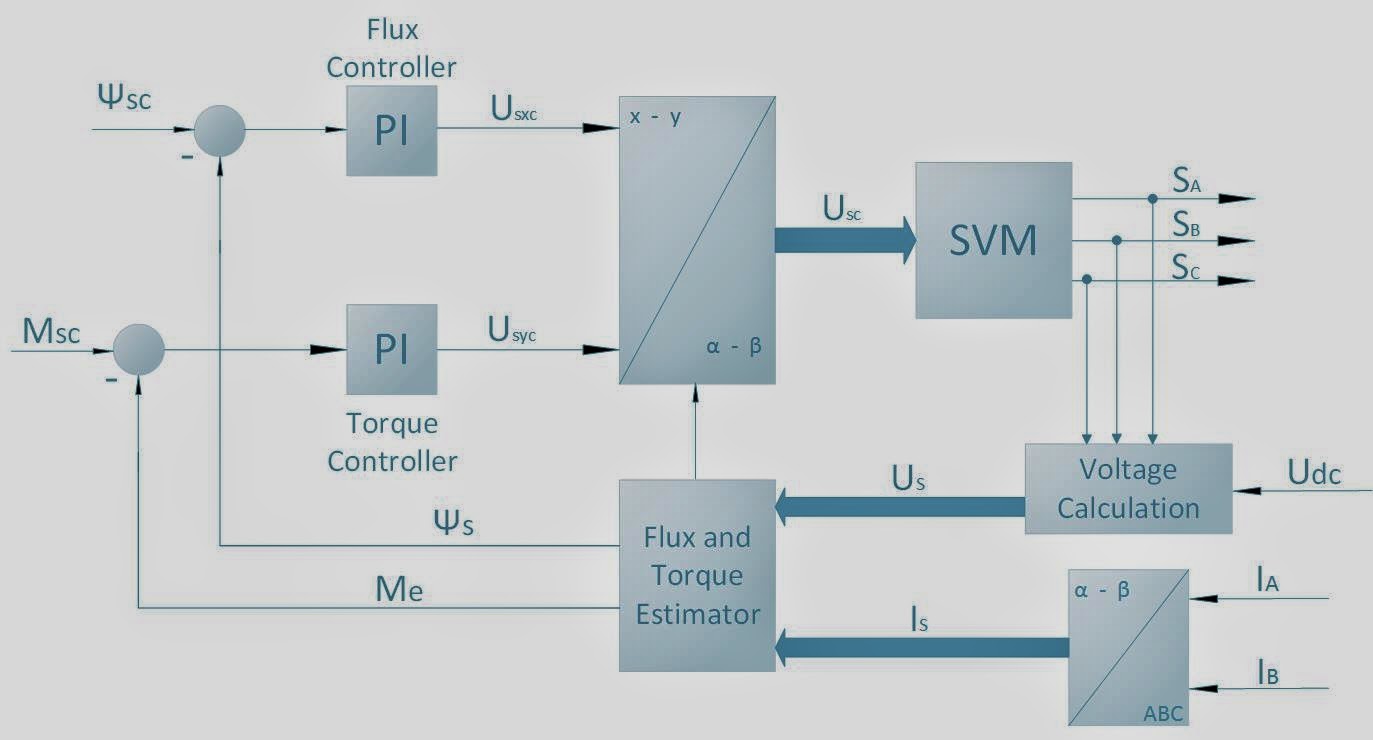
as simple as that for a separately excited DC motor. Figure shows the basic
structure of the vector control algorithm for the AC induction motor. To
perform vector control, it is necessary to follow these steps:
- Measure the motor quantities (phase voltages and currents)
- Transform them into the 2-phase system (α,β) using a Clarke transformation
- Calculate the rotor flux space-vector magnitude and position angle
- Compare this with reference flux and torque by using PI controller.
- The PI controller output is again converted to Clarke transformation and given to the SVM.

Thanks for taking the time to discuss this, I feel strongly that love and read more on this topic. If possible, such as gain knowledge, would you mind updating your blog with additional information? It is very useful for me.
ReplyDeleteacim
Excellent overview! Vector control really enhances the performance of induction motors, offering smoother and more efficient operation across applications.
ReplyDeleteFind out different motors here - Oriental Motor Distributor Philippines